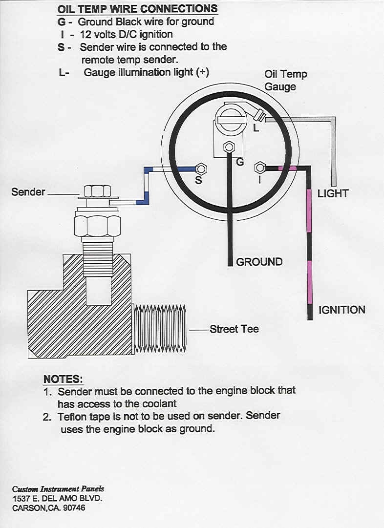
Are you looking to install or troubleshoot Autometer gauges in your vehicle? Understanding the Autometer Gauge Wiring Diagram is essential to ensure proper installation and troubleshooting of these gauges.
Why Autometer Gauge Wiring Diagrams are Essential
Autometer Gauge Wiring Diagrams are essential because they provide a visual representation of how the gauges are connected to the vehicle’s electrical system. These diagrams help users understand the wiring configuration, gauge connections, and power sources required for the gauges to function correctly.
How to Read and Interpret Autometer Gauge Wiring Diagrams
Reading and interpreting Autometer Gauge Wiring Diagrams may seem daunting at first, but with a little guidance, it becomes much easier. Here are a few steps to help you read and interpret these diagrams effectively:
- Start by familiarizing yourself with the symbols and color codes used in the diagram.
- Identify the different components of the gauge system, such as the power source, ground, and sensor connections.
- Follow the wiring paths from the gauges to the corresponding electrical components in the vehicle.
- Pay attention to any labels or descriptions provided in the diagram to ensure proper connections.
Using Autometer Gauge Wiring Diagrams for Troubleshooting Electrical Problems
Autometer Gauge Wiring Diagrams are not only useful for installation but also for troubleshooting electrical problems. By referring to the wiring diagram, you can easily identify any faulty connections, damaged wires, or incorrect installations that may be causing issues with the gauges. Here are a few tips for using these diagrams for troubleshooting:
- Check for loose or disconnected wires that may be causing a loss of connection.
- Verify that the power source and ground connections are secure and properly connected.
- Use a multimeter to test the continuity of wires and connections to ensure they are functioning correctly.
Importance of Safety When Working with Autometer Gauge Wiring Diagrams
When working with electrical systems and using wiring diagrams, it is crucial to prioritize safety to avoid any accidents or damage. Here are some safety tips and best practices to keep in mind:
- Always disconnect the vehicle’s battery before working on any electrical components.
- Avoid working on electrical systems in wet or damp conditions to prevent electric shocks.
- Use insulated tools and wear protective gear, such as gloves and safety goggles, when handling electrical components.
Autometer Gauge Wiring Diagram
Autometer Pro Shift Light Wiring Diagram – Diysus

Autometer Egt Gauge Wiring Diagram

Autometer Oil Pressure Gauge Wiring Diagram

Auto Meter Mechanical Temp Gauge Installation – YouTube

Wiring Diagram For Auto Meter Tachometer

How to Install an Auto Meter Sport Comp 5in Tachometer w/ Shift Light

Autometer Temperature Gauge Wiring Diagram – Wiring Diagram

Autometer Tach Wiring V8 – Unity Wiring
